hydraulic flow meter symbol
Adjusting the flow rate of fluid in a hydraulic system will directly impact the output. Start studying Pneumatics hydraulics symbols.
Hydraulic Symbols Zeus Hydratech
Spool type flow divider eg.
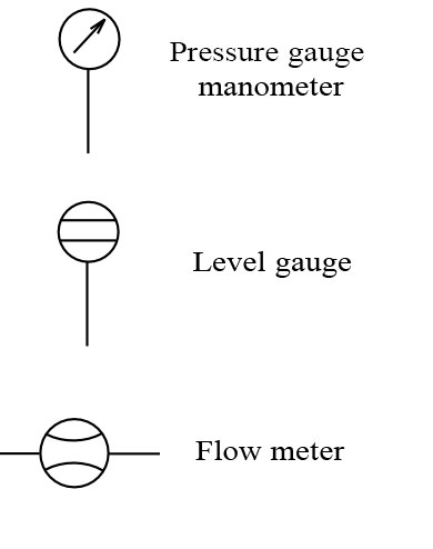
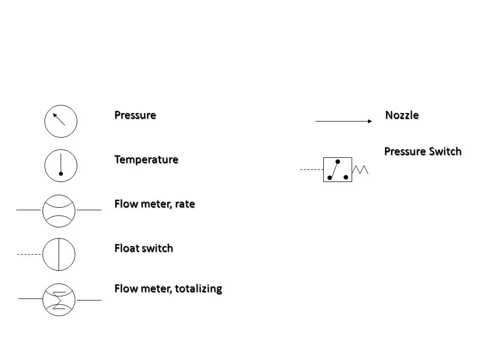
. The following are ISO hydraulic reservoir enclosure and meters schematic symbols commonly used on technical drawings. For different displays or electrical communication systems the flow meter symbol would remain the same but the symbol in the square connecting box would change. Pressure gauge manometer flow meter level gauge.
Standard PID Symbols Legend Industry Standardized PID Symbols. The arrows point into the symbol indicating the direction of heat flow. Show an actuator symbol for each flow path condition possessed by the component.
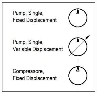
The bottom symbol has a side arrow that some manufactures have used to indicate a pressure compensated valve but in ISO 1219 now means a third bypass drain line. Temperature and pressure indicators are used to create a safety mechanism. PID PIP Sample Drawing.
Flow Wedge Meter Target Meter Weir Meter Ultrasonic Meter V-cone Meter Quick Change Pitot Tube Rotometer Double. Dc03 rotary flow divider. Use these flow meters to setup adjust and test hydraulic pumps motors cylinders and more.
Hydraulic power is based on Pascals Principle. The ability to determine a point of entry for removal of components or installation of gauges and or flow meters becomes quicker. Line Working Main Line Pilot For Control Line Enclosure Outline.
Dcl9-9-9-9r lowering valve with reverse flow check ecvf throttle with reverse flow check egeg. Hydraulic flow meter symbol The symbol shows a fluid flow meter with digital display. The only way to test a pump and motors safely and.
Air pilot second stage -Hydraulic. Sol first stage -Pneumatic. ISO Hydraulic Schematic Symbols Hydraulic and Pneumatic Knowledge Fluid Power Equipment.
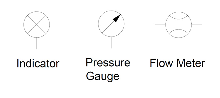
IEC 60617 Sample Drawing. Pressure gauge flow meter level indicator their designation of these devices is shown below. In hydraulic systems instruments are used.
Direction of Flow - Hydraulic. Function to control flow in some fashion the method of controlling the flow can vary dramatically. Inline Flow Meter for Petroleum Fluids One-Way Flow Ideal for monitoring pump performance and media flows in hydraulic systems.
Flow control wrrh reverse flow check cc. It is found at UsersPublicDocumentsAutodeskAcade. Electro-Hydraulic Valve Spring Gate Valve Balanced Diaphragm Gate Valve Slide Valve Metering Coke Post Indicator.
29 An arrow through a symbol at approximately 45. The hydraulic symbol library consists of all the hydraulic symbols. In some designs the actuator is supported by the bonnet.
A guide to common hydraulic symbols. If I have a hydraulic drill press when flow is turned on to the top side perhaps I have a clamp that I want to engage first. Pilot controlled spring centered.
Branching with connected pipe. Flow indicator flow meter tachometer torque meter pressure switch micro switch adjustable 2-way flow control with reverse flow check eg. In other designs a yoke.
Pressure exerted on a fluid is distributed equally applied pressure is equal to desired pressure. Ivcrd 2vcr adjustable 3-way flow control with reverse flow check eg. Pressures up to 6000 PSI 414 bar.
AC500 PLC COMM INT Modules. I vcrt3vcr adjustable 3-way flow control flow divider spool type flow divider cc. Miscellaneous hydraulic symbols and devices used in hydraulic circuit design.
ISO Hydraulic Reservoir Enclosure Gages and Meters Schematic Symbols. Dc03 rotary flow divider cc. Insert hydraulic components from the icon menu.
Direction of Flow - Pneumatic. Learn vocabulary terms and more with flashcards games and other study tools. However the reduced flow is lower than that of the meter in flow control.
Ivcrd2vcr adjustable 3-way flow control wr1tå reverse flow check cc. IEC 60617 Sample Drawing. By reading a schematic and following its.
By understanding the symbols and following the flow path of the schematic success in determining a problem with your system becomes quicker and more rewarding. JIC NFPA Sample Drawing. PID PIP Sample Drawing.
28 Each symbol is drawn to show normal at rest or neutral condition of component unless multiple diagrams are furnish shown various phases of circuit operation. Hydraulic schematic symbols to DIN ISO 1219. Muffler with flow.
Hydraulic Schematic Symbols-spring -roller -rollerone direction only Electrical Control-Solenoid the one winding Pilot Operation-pneumatic -hydraulic Pilot operated two-stage valve-Pneumatic. Sol first stage -Hydraulic. Flows up to 150 GPM 568 Lpm.
JIC NFPA Sample Drawing. 2 A valve is a mechanical device that controls the flow of fluid. The hydraulic symbol library in AutoCAD Electrical includes filters valves cylinders pressure switches motors pumps meters restrictors quick disconnects flow arrows and more.
Hedland Flow Meters Badger Meter Inc H621-016 - Flow Rate Hydraulic Flow Meter - 16 gpm Max Flow Rate 1 NPTF in Port Size. Ivcrt 3vcr adjustable 3way flow control flow divider eg. Hyd pilot second stage Check valves Shuttle valves.
7 rows Hydraulic Symbols. The top symbol shows a curved restrictor but the symbol also has a line with a dot that has previously been used to indicate temperature compensation.
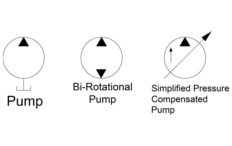
Hydraulic Symbology 205 Hydraulic Pumps
Hydraulic Circuit Schematic Showing The Location Of The Flow Meter Used Download Scientific Diagram

Design Elements Fluid Power Equipment Fluid Power Equipment Vector Stencils Library Symbol For Thermometer In Pneumatics

Volumetric Flow Meter With Digital Display Measuring And Display Devices Fluid Power Hydraulic Symbols Services Festo Didactic
Hydraulic Symbols Zeus Hydratech
How To Read Hydraulic Circuits Schematic Hydraulic Symbols To Din Iso 1219

A Guide To Common Hydraulic Symbols Engineeringclicks
Bliznjice Zahodni Ti Si Flow Meter Symbol Marchgourdmadness Com
Flow Sheet Symbols Roy Mech
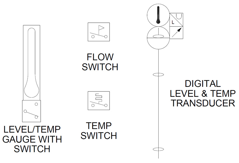
Hydraulic Symbology 305 Condition Monitoring Symbols

Fluid Power Symbols Ppt Download
Badger Meter Petroleum Fluid Flow Meter 701 030 Hydraulic Supply Co
2
Hydraulic And Pneumatic P Id Diagrams And Schematics Inst Tools

Flow Meter Hydraulic Misc

Common P Id Symbols Used In Developing Instrumentation Diagrams Learning Instrumentation And Control Engineering
Hydraulic Symbology 305 Condition Monitoring Symbols

Hydraulic Symbols Zeus Hydratech

A Guide To Common Hydraulic Symbols Engineeringclicks